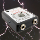


Delay circuit for (high speed) photography


This article describes how to build a simple uC based delay circuit for
photographic applications like drop or high speed photography. It can be used
to control the trigger lag of cameras and flash units, generate a periodic
trigger pulse or even control magnetic valves. The input and the three outputs
of the circuit use standard 3.5 mm stereo jack connectors, so the delay element
can be looped easily into your existing trigger circuitry like the SmaTrig for example. Cascading multiple delay devices
into more complex circuits is easily done.
As simplicity was an important design goal, there is no text display or a
sophisticated analog input stage. All resources to build a copy of the delay
are provided below in the Download section.
Usage

A short press of the on/off button switches the circuit on and off. By holding the on/off button down while switching on you can cycle through the three time ranges indicated by the LEDs. The chosen operating range is saved in the EEPROM so the uC will remember the last setting after switching off or even removing the battery.
Standard delay mode
Directly after programming the AVR your delay will work as described in this section. The delay time is set by two potentiometers. The left one is used for the coarse time setting (0-100% of the chosen range), the right one allows fine tuning (0-10% of the chosen range) of the delay time. Both knobs turned to the maximum will result in 110% delay time (1.1 s, ...). The functions of the wheels are:
| Function | Red LED | Yellow LED | Green LED | |
| Left wheel | Delay 0-100% | 1 s | 0.1 s | 0.01 s |
| Right wheel | Delay 0-10% | 0.1 s | 0.01 s | 0.001 s |
The coarse/fine solution proved to be very
convenient in practical use (dark room). For drop photography, the absence of a display
turned out to be unproblematic, because you keep your eyes on the drop and not the delay
while adjusting the time.
The manual trigger button allows to simulate a trigger event and is useful for
lighting adjustment or general testing. It just shortens out the input contacts.
The duration of the trigger pulse in this mode is always 0.35 s.
The minimum lag of the circuit in the green mode for both potentiometers set to
0 is about 12 us (microseconds). Use this setting if you like to use the delay
circuit just as a repeater to fire for example three different flashes from one
source. The lag will be negligible in most cases.
Delay / pulsewith mode
There are applications where it would be useful to have control over the duration of the trigger pulse width. Examples are bulb mode shots or the generation of drops with magnetic valves. For such special cases the delay circuit can be switched to a different mode, where the right rotary knob changes it's function form fine tuning the delay time to controlling the trigger pulse duration. The resulting functions and times are:
| Function | Red LED | Yellow LED | Green LED | |
| Left wheel | Delay 0-100% | 1 s | 0.1 s | 0.01 s |
| Right wheel | Trigger pulse width 0-100% | 1 s | 0.1 s | 0.01 s |
To toggle to this operating mode press the on/off button for more than 6 s while switching on the device. The LED will cycle through the ranges twice and start to cycle faster. If the delay / pulse-width mode is enabled, the LEDs will blink once after switching on. Follow the same procedure to toggle back to the standard coarse/fine mode.
Interval timer
Short-circuiting the input permanently (connect tip and shaft in stereo jack plug or block the trigger button) will result in periodic self-triggering. This way a simple interval timer can be realised. The interval period will be the sum of the delay time, the trigger pulse duration and the internal re-trigger blockage time of 150 ms. Accordingly the maximum achievable frequency will be about 6.6 Hz.
100x slow mode
For some slow processes the delay range of 1 s might be too short. By connecting pin 6 and 7 of the uC together (see marking in image above) the time ranges are increased by a factor of 100. Correspondingly they change to: 100 s, 10 s, 1 s. All other changes must be done in the AVR C code. Note that the pins are checked once when the circuit is switched on.
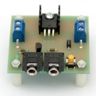
The Circuit

The circuit is based on the ATtiny24 AVR by Atmel. With its 14 pins the
controller is a good compromise between the very small Tinys and the bigger
ATmega types. The controller is connected permanently to the battery, because
it draws less than 0.5 uA in off-state (sleep mode). In active mode the current
consumption is about 5-6 mA. The potentiometer voltages are converted into
8 bit digital numbers by the internal ADC of the AVR. The input pin voltage
comes from the internal pull-up resistor. I think, the other components
don't need an explanation. The second and third output can be omitted if not
needed. The diodes at each focus line are necessary to avoid a
permanent connection between the shutter and the focus wire. Otherwise pressing
the shutter button half-way will trigger the camera. For Canon cameras or
flashes, the focus wire isn't necessary for triggering.
The chip should be mounted
on a socket to allow re-programming. The battery is the common 2032 lithium
cell. Do not forget to solder the wire bridge under the battery holder. It's
the minus of the battery. The capacitor can be omitted.
The single sided PCB layout can be downloaded below in Eagle format or a PDF.
The trace clearance is rather DIY friendly. The PCB has a size of 68 mm x 50
mm.
In the EU all parts can be bought at www.tme.eu or
www.segor.de.


C code
The AVR is programmed in C (AVR Studio). You can download the source code below. The code may serve as an example of how to:
- use ADC in continuous mode
- switch ADC ports
- use the pin change interrupt
- poll a button
- write and read EEPROM
- use timers
- use the sleep mode
on the ATtiny24. Changing fuses is not necessary.
Troubleshooting
- No reaction after assembly
- Jumper below battery forgotten? It is the minus pole.
- Jumper below battery made of insulated wire? The battery needs contact with the wire.
- Battery inserted correctly? The chip gets hot when the voltage is reversed.
- uC inserted correctly? Compare your circuit to the images above.
- uC programmed correctly? The supply current after power-on should be < 1 uA.
- Focus triggered permanently
- Correct polarity of diodes? The "standing" mounting of the diodes is prone to polarity errors.
- Focus or shutter not triggering
- Forgotten to solder a pin in the sockets?
- Mechanical problem of socket? Plug in and out with some force.
- Fried the transistor with an old high voltage flash? Replace the transistor.
Download
delay2.c - C source code version 2
delay2.hex - flash file for ATtiny24 version 2, works with version 1 too!
Makefile - Makefile for project
delay2.sch - Eagle schematics
delay2.brd - Eagle board file
delay2_pcb_A6.pdf - PDF of board version 2
partlist2.pdf - part list
Links
http://www.dslr-forum.de/showthread.php?t=837474 - A thread about the circuit in the dslr-forum (in German)
SmaTrig 2.1 - A 15-in-1 trigger with light barrier support for drop photography
Contact
You can contact me if you have suggestions, spare material requests or other questions. My address is

Please use "Delay (your_camera_type)" as subject.
Good luck with building your delay. Pics are welcome!
Gallery


Old version of the dalay circuit

This article describes a uC based delay circuit for photographic applications
like drop or high speed photography. It can be used to control the trigger lag of
cameras or flash units. The input and output of the circuit use
standard 3.5 mm jack connectors, so the delay element can be looped into your
existing trigger circuitry like the SmaTrig for example.
As simplicity and budget components were important design goals, there
is no text display or any sophisticated analog input stage. The circuit allows
three delay ranges which are indicated by LEDs:
- 1 s, red LED
- 0.1 s, yellow LED
- 0.01 s, green LED
A short press on the button switches the circuit on and off.
The range is chosen by holding down the button when switching on the delay.
The current range is saved in EEPROM so you don't have to set it each time.
The actual delay is set by two potentiometers. The left one
is used for the coarse time setting (0-100% of the chosen range), the right one allows finer tuning
(0-10% of the chosen range) of the delay time. The coarse/fine solution proved to be very
convenient in practical use (dark room). For drop photography, the absence of a display
turned out to be unproblematic, because you keep your eyes on the drop and not the delay
while adjusting the time.
The minimum lag of the circuit in the green mode for both potentiometers set to 0 is
about 12 us (microseconds).
The Circuit

The circuit is based on the ATtiny24 AVR by Atmel. With its 14 pins the controller is a good
compromise between the very small Tinys and the bigger ATmega types. The controller
is connected permanently to the battery, because it draws less than 0.5 uA in off-state
(sleep mode).
The potentiometer
voltages are converted into digital numbers by the internal ADC of the AVR.
I think, the other
components don't need an explanation. The second output can be omitted if not needed.
The parallel transistors at each output are necessary to avoid a permanent connection between the shutter
and the focus wire. Otherwise pressing the shutter button half-way will trigger the camera. With Canon cameras
or flashes, the focus transistor can be dropped completely. You can also use a diode instead
(cathode to shutter, anode to focus).
The chip should be mounted on a socket for easier programming. Three types of
batteries can be used with the PCB: CR24xx print type, CR20xx print type or two
AAA batteries when the battery holders are used, see title image above.
The PCB layout can be downloaded below in Eagle format or a PDF. The trace clearance is
rather DIY friendly.

C code
The AVR is programmed in C (AVR Studio). You can download the source code below. The code may serve as an example of how to:
- use ADC in continuous mode
- switch ADC ports
- use the pin change interrupt
- poll a button
- write and read EEPROM
- use timers
- use the sleep mode
on the ATtiny24. Changing fuses is not necessary.
To do
If you like to further improve the circuit I recommend to
- add button to simulate a trigger event (just pull input to ground)
- add a programming port
Download
delay.c - C source code
delay.hex - flash file for ATtiny24
delay.sch - Eagle schematics
delay.brd - Eagle board file
delay.pdf - PDF of board
partlist.txt - part list
PHP Scripts Temporary Email Throwaway Email


|
Last modified: Sun April 14th 2024 Copyright © 2024 www.doc-diy.net |
Best regards
Don