

SandBox - Lathe-mounted disk sander
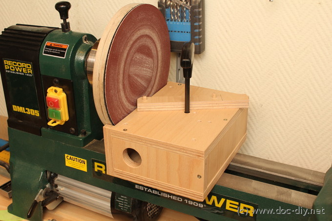
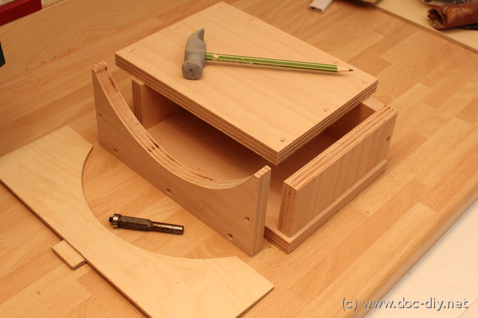
No, it's not a hamster house under construction in the title picture.
It's a simple attachment for the lathe to turn it into a disk sander.
The idea of such a device is not unique. The whole trick is to build
something simple, yet functional. My priorities for the project were:
Reasonable dust extraction, compact size, easy to attach and easy to build.
Below you'll find instructions how to build the lathe extension.
The Disk
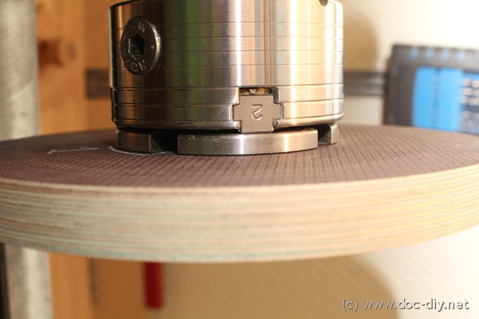
I started with the disk made of thick coated plywood. Since I have the chuck
with 50 mm jaws mounted most of the time, I turned a recess into the disk.
For best stability and biggest possible support area on the chuck, the
recess diameter is chosen just below the maximum possible jaw expansion.
Make sure, the jaw expansion presses the disk entirely on the plane area of
the jaws. This will guarantee a wobble-free run.
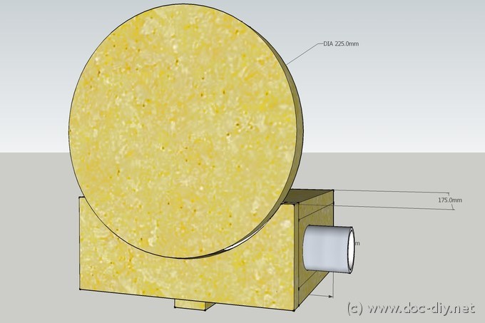
Once the mount feels save, the outer diameter can be turned to an exact
value. Make sure you choose a common sand paper diameter. I chose 225 mm.
My midi lathe
(Record Power DML305) allows 305 mm as maximum.
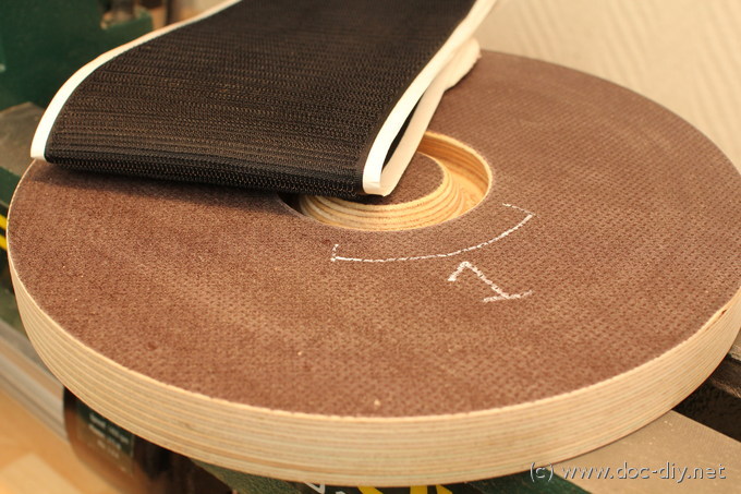
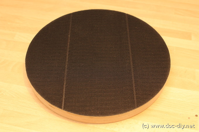
In the next step the Velcro strips or sheet is attached.
Clean the surface before. It's the rough side with the hooks you have to put
on the disk. Put the strips in a way you don't end up with a very thin
strip at the border. It might get loose when removing the sand paper.

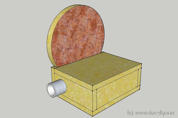
The Box
The dimensions of my box are 216 x 175 x 90 mm (ca. 8.5 x 7 x 3.5 inch) for
a 225 mm disk, see CAD image below. I'd recommend now to build the box sightly
wider to be able to use the full disk width even with the fence attached.
The body
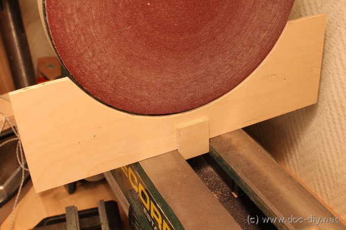
is built of six rectangular pieces. Only one side has a circular cutout
following the disk contour with a small gap. I cut out a stencil for the arc
and copied it with a flush trim router bit.
Effectively, all air sucked in by the dust extractor passes the rotating
sanding disk either through the front gap or the circumferential gap, despite
some leakages through the wrench hole.
This guarantees an almost ideal dust extraction even at very low
volume flows. Effectively, you can operate the connected vacuum cleaner at the
silent lowest power setting.
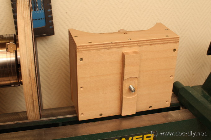
The mounting of the box is shown in the pictures below. After going through
different concepts I decided to make use of the 8-mm Allan T-wrench supplied
with the Nova chuck and always (f)lying around the lathe.
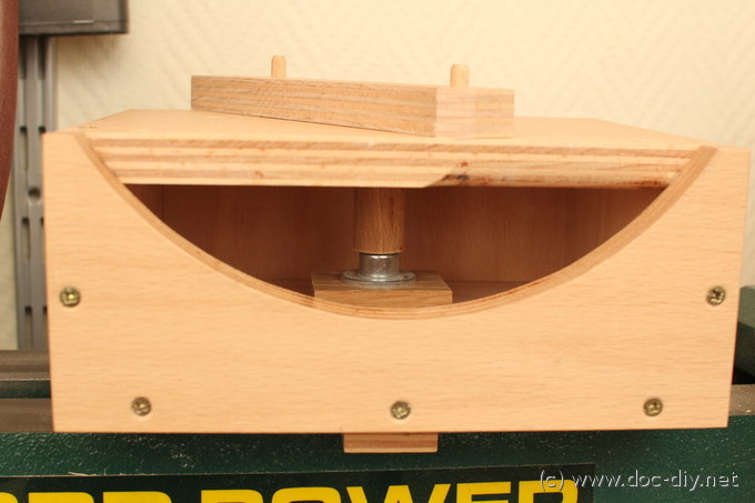
A M10 hex head screw
is located inside the box and is accessed through a hole from the top.
A wooden sleeve guides the wrench to the screw for smooth handling. It also
reduces the air leakage when sized properly.
A practical advantage of the concept shown here is the relatively short screw
length needed (60 mm, 2.5 inch). Longer M10 screws might be hard to source.
Alternatively a bicycle quick release can be used with the lever side at the
bottom.
The pivotable fence is built in a very simple way using dowels. The angle is adjustable to 30, 45, 60 and 90 degree. I clearly prefer fixed but precise angles over a fake precision angle scale, very common in cheap woodworking tools.
CAD model
A Sketchup model of the lathe disk sander is available here. I built the model to be able to set up the flow simulation described below.

Numerical Flow Simulation (CFD)
In the colorful images below you'll see a flow simulation of the air in the box
and around the disk. The idea behind such a simulation is to divide the air
volume into small boxes (750000 here) and let the computer calculate the flow
properties in each box by solving physical equations. This might take form
minutes to weeks depending on the problem size. This science discipline is
called Computational Fluid Dynamics (CFD).
The simulation has been done using OpenFoam and
visualised using ParaView. Both software
packages are freely available.
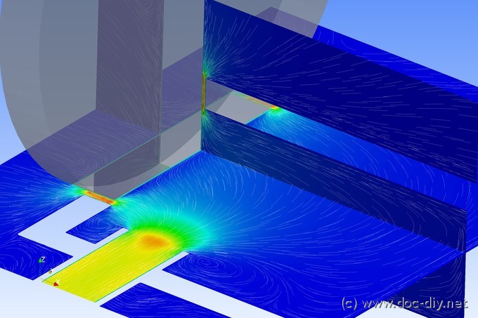
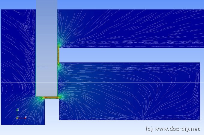
The images show the air velocity distribution around the disk and in box when
"vacuum" is applied to the box outlet. The colour stands for the velocity
magnitude while the stream lines indicate the flow direction. The disk rotation
is modelled by imposing a rotational speed at the disk walls.
The most interesting region is the slit where the box top and the disk meet.
Two forces act on the air there: The disk entrains the air and pulls it in the
local rotation direction. The low pressure in the box tries to sucks the air
into the box.
On the side of the dust outlet where disk moves down, both forces point into
the box. On the other
side the disk tries to pull the air (and dust) away from the box. The air
is "undecided" and leaves partially the box. This is an area of bad duct
extraction.
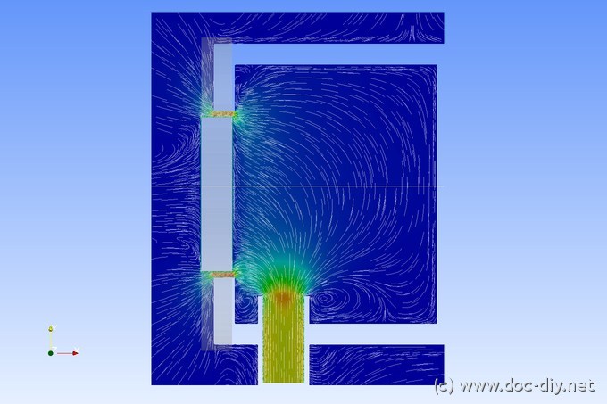
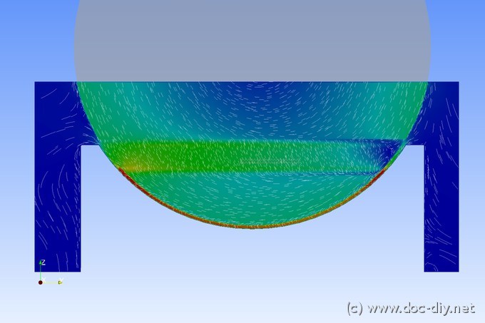
The last CFD image shows a slice in the gap. The velocities are lower on
the right and the streamlines more chaotic. Moving the visualisation plane
very close to the disk would show that all the air follows the disk.
To put it in the nut shell: Sanding on the left will make no dust,
while dust extraction will not work when sanding on the right.
Throwaway Email Disposable Email Throwaway Email


|
Last modified: Sun April 14th 2024 Copyright © 2024 www.doc-diy.net |