

DIY opto-isolated power switch


When microcontroller circuits interact with real life,
switching lamps, motors or solenoids might become necessary.
Switching such "non-digital" loads is usually a bottle neck in DIY projects,
because nobody wants to have 230V or 110V swirling around on
his perfboard.
Driven by the need to control a big lamp for time lapse shooting
with the SmaTrig I designed a compact
power switch useful for DIYers and electronics hobbyists.
In the following I'd like to share with you the thoughts and ideas
that went through my mind during the development of the device
and provide all data necessary to build your own switch.
The ideas
There are two basic safety requirements for the described power switch. First, we need a galvanic isolation of the low voltage side from the high voltage side. This allows you to work safely on the control circuit while connected to the grid and protect fragile and expensive equipment like cameras or computers. Opto-isolated devices like opto-triacs or opto-SSR (solid state relays) are perfect for this task. Fortunately there are dozens of readily available components on the market. Sharp offers for example a whole spectrum of devices with up to 16 A switching capability.
The second requirement is the electrical insulation of the high-voltage side or in the best case of the complete switch. This means, the whole circuit should be encapsulated in a plastic enclosure. I have chosen a universal enclosure with an integrated power plug and socket. This choice allowed me to reduce the often underestimated "mechanical engineering" to the minimum. These enclosures contain usually mounting bolts for a PCB so you just need to drill holes at the right positions in your PCB to mount it. It is a good idea to pick an enclosure with ground contacts in the plug and the socket for maximum safety.
And lastly, when putting the effort into building something on your own, the final work should feature something special, making it better than commercially available products. Following this idea I incorporated an inverter function and an indicator LED. In normal operation (depressed button) the switch is in OFF state and turns ON when a switching signal is applied. In the inverted mode, activated by pressing the button, the switch is ON in neutral state and goes OFF when the switching signal is applied. This way the button can be used to manually switch the load and "override" the switching signal for testing or troubleshooting. The switch states are summarised in the following table.
| Button | depressed | pressed |
| Input open | OFF | ON |
| Input pulled down | ON | OFF |
The input port is a standard 3.5 mm stereo jack socket. To activate the switch the tip and the shaft (ground) of the jack must be shorted out. This principle is also used to trigger cameras and photo flash units. The switch is directly compatible with the SmaTrig.
The circuit

The schematic of the switch is shown in the image above. I will explain the
operation step by step.
The key element of the circuit is an opto-isolated solid state relay (SSR) by Sharp.
I have chosen a part named S216S02 specified for 16 A and 600 V with built-in
zero-crossing (ZC) circuit. Several versions of the chip exist, see
sharp-world.com for more details.
The S202S12F even incorporates
a snubber circuit making C3 and R2 unnecessary on the board.
The determination of the values of C3 and R2 is rather tricky and depends very much
on the application. The values 100 nF and 47 Ohm are the proposed values in the
data sheet.
The transformer, the rectifier and C1 form the power supply for driving the IR-LED
in the SSR and the signal LED. These parts can be replaced by a durable battery
in case the ON periods of the switch are short. When using a CR2032 with a nominal
capacity of 200 mAh the total ON time will be about 10 h because of about 20 mA needed
to drive the LEDs. It's ok for switching on a lamp for a few seconds but will reach
just for just 20 h when controlling for example a fridge with 50% duty cycle.
Ok, let's come to the non-trivial part - the control circuitry built around the
transistors Q1 and Q2. The depressed state (SW1 like on schematic) will be described
first. The base of Q1 is pulled up by R4, so Q1 is conducting since it's an NPN. The
base of Q2 is connected to the input plug and pulled up by R5. If the input is open,
Q2 is closed since it's an PNP. If the input is closed (short-circuited) the
gate of Q2 is pulled to ground via R3 which is "stronger" than R5. Q2 opens.
The circuit works also without R5 but is too sensitive resulting in possible
relay chatter.
In the pressed state the base of Q1 is connected to the input and pulled up by
R4. The base of Q2 is permanently on ground via R3, so it's permanently open.
Now when the input in shorted Q1 closes and the relay turns off.
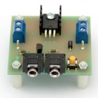
The board

The PCB layout is shown above. The Eagle files are available for download below, so
you can easily adjust the dimensions to your needs. Many manufacturers have
technical drawings of their products online. The enclosure I used was
the model SG322 by Strapubox.
My design goal was to mount all the parts directly on the PCB to avoid unnecessary
wiring. Special care was taken to ensure proper clearance
between the logic and high voltage side. It's minimum value is about 8 mm dictated
by the pinning of the SSR chip. The PCB is additionally coated with plastic paint
for insulation.
Important: In case the switch current exceeds about 2 A you should:
- attach a radiator to the SSR, see data sheet for details
- reinforce the PCB traces on the high voltage side with copper wire
My prototype is shown below. Unfortunately I left the PCB in the etching machine for loo long, so the traces looked terrible. I rerouted them with tinned copper wire.

Building and usage of the circuit shown here is at your own risk. High voltage is nothing for electronics novices. Do not eat any of the electronic parts!
Downloads
powerswitch.brd - Eagle board layout filepowerswitch.sch - Eagle schematic file
Feel free to feed back any ideas for further improvement or simplifications.
Temporary Email Temporary Email Throwaway Email


|
Last modified: Sun April 14th 2024 Copyright © 2024 www.doc-diy.net |