

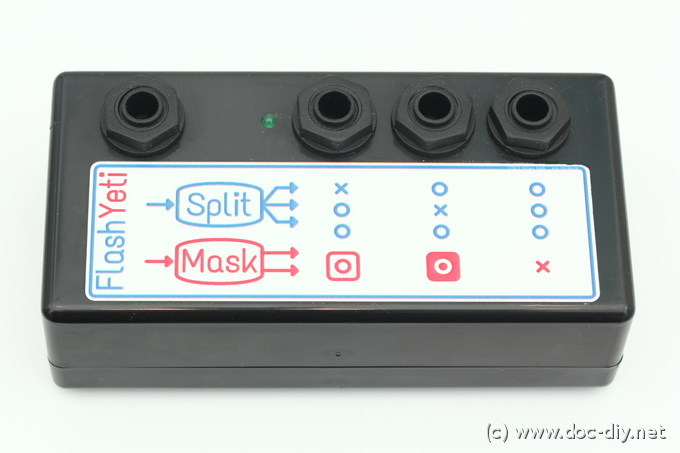
FlashYeti - photo flash splitter and masking switch
The presented circuit combines two functions often needed by photographers.
It can operate as a splitter or multiplier and allows connect three
(up to 6 with splitters) different photo
flashes to a camera or radio control. It's capable of triggering older
high voltage photo strobes or mixing new and old devices.
The second function is less known but very practical when objects are to be
isolated form the background. This is a typical task for a product of stock
photographer.
The image is built in two steps: a traditional well illuminated image of the
object, and a second image of the background with a black silhouette of the
object. The background image serves now as a mask for the first one.
The essential thing now is to have the images matching. Any movement of the
(human) object make the mask useless.
The task of the FlashYeti is now to switch between two different flash groups
for each shot: front, back, front, back and so on. With modern cameras allowing 10
shots per second and the flashes switched automatically the problem of a
moving photo model or object disappears.
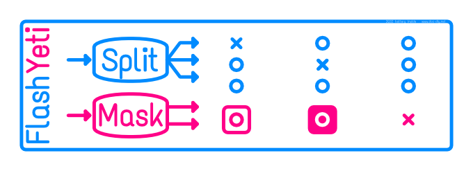
So how to tell FlashYeti it should act as a splitter or as a masking switch?
That's easy. Whenever a jack plug is plugged into the last rightmost socket,
the FlashYeti becomes a splitter. If the last socket is free, it becomes a mask
switch switching between the other two sockets.
The leftmost socket is always the input and should be connected to the
camera or your radio control receiver.
The label explains the functions for all possible plugging options.
How to use a mask switch?
The procedure of creating a mask is explained in this section on a practical example. The technical setup is shown below.
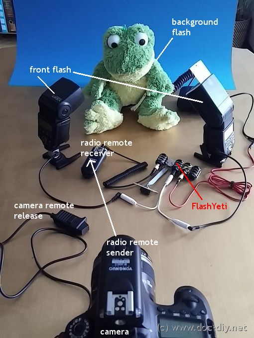
The flashes illuminating the photographed object are connected to the fist
channel of the FlashYeti. An audio Y-cable is used to drive two flash units from
the single output. The second channel is used for the background flash
which is hidden behind the object. To avoid an offset between the mask image and
the actual object image a tripod should be used.
After everything has been hooked up correctly, images similar to those below
should come out.
 Nicely iluminated object (and background if needed)
 Overexposed background (white) and dark foreground
Now the exposure of the mask image needs to be adjusted to be all black in the area of the frog and all white around it. This can happen by a simple curves adjustment or some manual brushing. The quickest and most radical treat is a threshold operation, but you will loose the translucency gradient in the border area. Hair might look pixelated. Partly translucent objects will become either fully opaque or fully transparent. Keeping the gradient can give a stunning see-though effect.
 Adjusted mask image converted to grayscale
Let's now overlay the masked image with a new background. I picked something totally different from the original background.
 New background image
The result of the overlay is shown below, it's Kermit in purple salad land. You might have noticed I cheated a little. The result image is slightly bluish in the corners because I didn't whiten my mask completely as in the image above.

The more interesting part is the transition area around the frog shown in the close-up below.

Not bad, isn't it? The fur looks pretty natural and the loop even has some
see-though spots. The gradual mask pays off here and you will never achieve
such a precision by manual path isolation.
What you see here is of course the best you can get out of the automatic
masking method. If you have a
real living model you will need a very short interval between the front and the
mask shot. This interval is only limited by your camera. FlashYeti allows
extremely short intervals. Since you flashes fire sequentially the charging time
is not an issue too.
Masking in Gimp
I'll just provide the idea of how to proceed. Please refer to other sources for a detailed instruction.
- Load the front, mask and background image as layers.
- Add a mask to the front image, black or white, doesn't matter.
- Select the mask layer, copy it (Ctrl-C).
- Select the mask of the front image and paste the mask into it (Ctrl-V).
Masking with Imagemagick's convert (command line)
The masking operation can be done within seconds in a command line
without using a GUI. This might be very handy in automated scripts
or if you repeat the operation many times.
All you need is the imagemagick
package which is usually preinstalled in all Linux distributions.
The sequence of commands given below can be used with the images
above. Just download them into a folder and type the commands.
This command adjusts the levels (10% blackpoint, 50% withe
point, gamma) and negates the mask.
convert flashyeti_mask32_680.jpg -colorspace gray -level 10%,50%,1 \
     -negate mask_rdy.jpg
Now the mask is applied to the object image so it becomes
partially translucent.
convert flashyeti_foreground32_680.jpg mask_rdy.jpg -alpha Off \
     -compose CopyOpacity -composite frog_masked.png
The masked image and background are finally merged. The translucency
infomation is discared.
convert flashyeti_bg32_680.jpg frog_masked.png -flatten result.jpgThat's all!
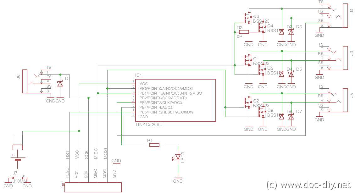
The Circuit
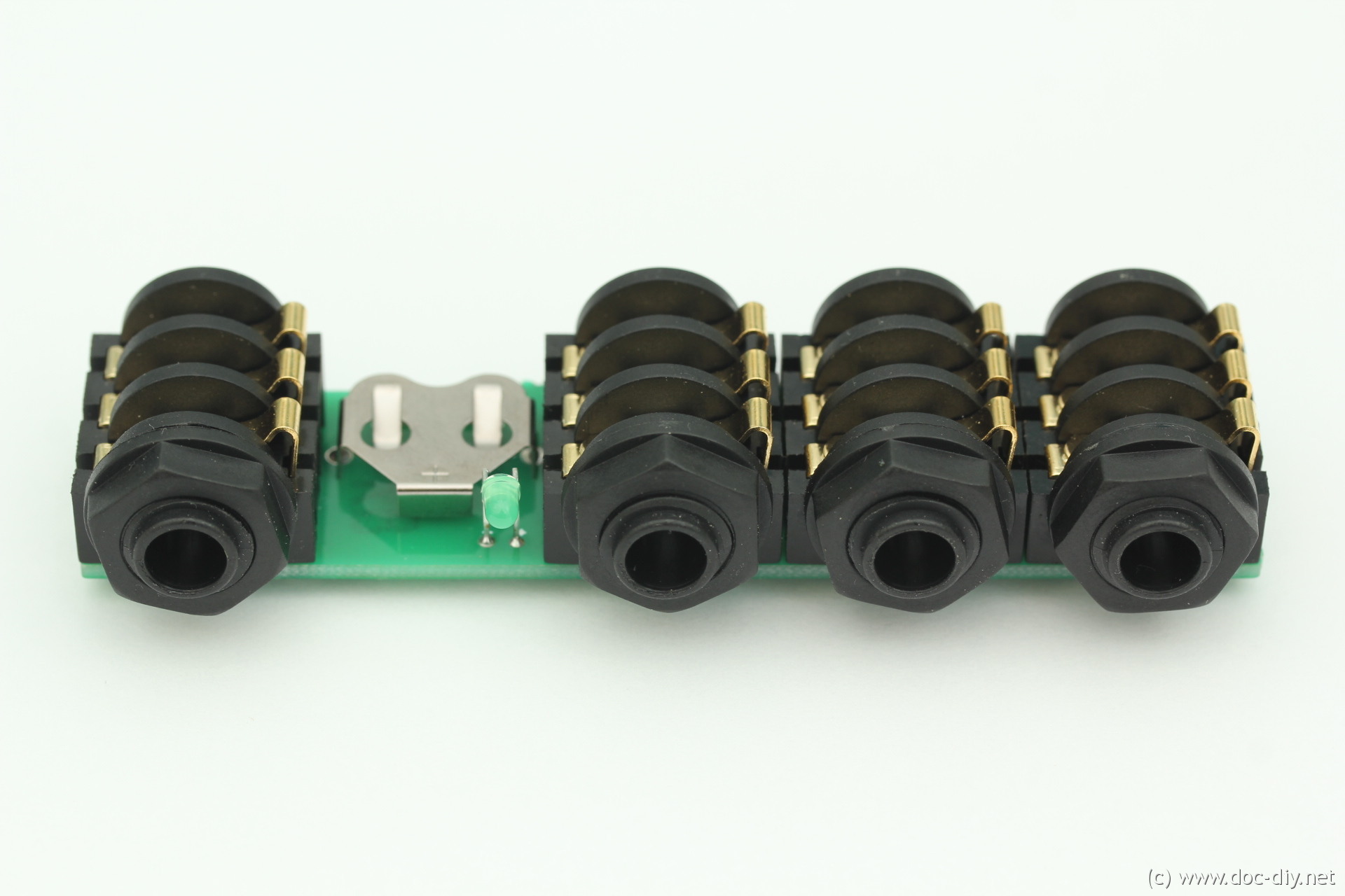
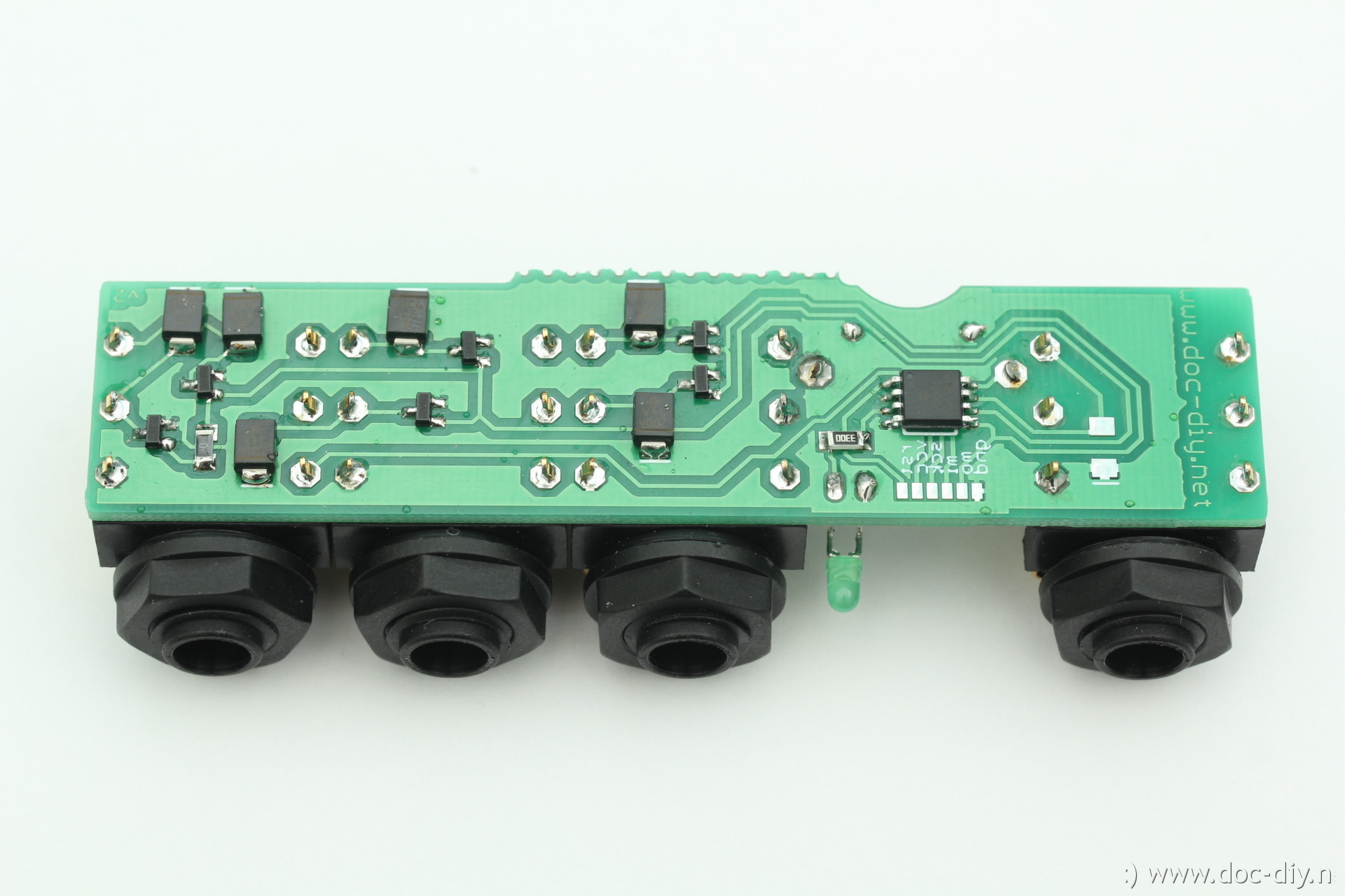
The heart of the circuit is the AVR ATtiny13 microcontroller. It drives the
outputs in two groups via N-MOSFETs. The input is connected to an external
interrupt pin. The microcontroller checks if the most right output socked is used or not
and switches between the splitter and the masking switch mode. The battery is
connected permanently, since the chip is in power-down mode all the time, except
the few seconds where the input changes and something needs to be done.
If the usage of the FlashYeti is not extremely extensive, the lithium coin
battery (CR1632) should last for many years.
There are some over-voltage protection components at the exposed points like
the input and the outputs. They are optional.
An LED indicates the state of the circuit with short blinks.
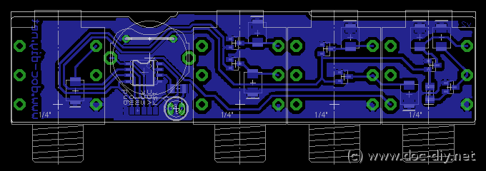
Component recommendations
The 6.3 mm sockets are Neutrik Rean NYS 216 (G). They are cheap, sturdy and
occupy less PCB space then other types.
The version of the AVR plays no role as long as it has a tiny13 in the name.
A big variety of MOSFETs fits the circuit. Get one that fully opens at
Vgs = 3 V or lower (logic level type). The higher the allowed
drain-source voltage the better. Vds > 200 V will give you
some extra robustness and makes the device compatible to old high voltage
flash units.
If you use protection diodes, select the voltage at the upper end of the
transistor voltage. In normal use, the only danger for the FlashYeti are
old high voltage triggered flashes.
If you are sure not to operate the device with very old photographic equipment
you can omit the protection components, which might be hard to get in the
desired voltage ratings.
If you add protection diodes, use unipolar types. The cathode (marked
with a white dot or line on the component) should be connected to the signal
side, not the ground!
The LED resistor should have a value between 220R and 1k depending on the
desired brightness. 330R is a good compormise.
Enclosure and label
Putting the assembled circuit into an enclosure is extremely easy since all
the holes are on the same side and are in-line. The inner volume of the box
must be at least 102 x 35 x 25 mm (W x D x H).
This equals to 4 x 1.4 x 1 inch.
A (hopefully) self-explanatory label for the FlashYeti is shown below.
Download
The Eagle files for the PCB, the HEX file for the microcontroller, the label and the drillaid PDF can be downloaded here: FlashYeti.zip. Programming of the EEPROM and the fuses of the microcontroller is not required.
PHP Scripts Disposable Email Throwaway Email


|
Last modified: Sun April 14th 2024 Copyright © 2024 www.doc-diy.net |
ich würde gerne einen fertigen FlashYeti kaufen oder einen Bausatz.
Würde mich über eine Rückmeldung freuen.
Grüße aus Ffm
many thanks
würdest du mir bitte zwei dieser Geräte anbieten.
LG, HaJo
thank you for your answer and explenation of the technical isuse.
Thorsten
yes, the front-back switching is based on counting. Fist (3rd, 5th...) camera trigger pulse fires the front, the second (4th, 6th...) the back. It there is no pulse for longer then about 2 s, the device resets and starts counting from 1 (front flash) for the next shot.
Luk